Undocumented Features
This page is still incomplete. Please contribute by clicking on the Edit this page on GitHub link at the bottom of this page.
Table of Contents
 Introduction
This page lists features that were intentionally removed from the documentation by Padauk, but are still available in several microcontrollers. In some cases the reason for this seems to be marginal performance, in other cases the reason is not entirely clear.
Please keep in mind that using these features in your design comes with some risks:
- They may cease to work under certain circumstances, for example increased temperature.
- It is likely that Padauk is not testing these features in their production testing. Therefore you may encounter devices where these features are defective.
- Padauk may remove these features from their products without notice.
16 MHz System Clock (All MCUs)
The CPU system clock is configured in the clkmd register that is present on all MCUs. The highest clock speed setting is 8 MHz, derived from dividing the clock speed of the internal high-speed RC oscillator (IHRC) by two. A setting for a clock divider of one is absent from all devices. Notably there is a bit combination marked as reserved.
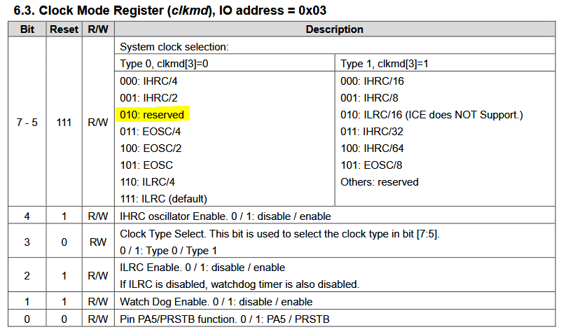
Selecting this bit combination will set the clock divider to one and will therefore allow setting the system clock to 16 MHz. One issue is that the MCU is only stable at this clock at a relatively high supply voltage (VDD) close to 5V. For example, the minimum voltage where the PFS173 can be clocked at 16 MHz is 4.0V. Most likely even higher voltages are required at temperatures higher than room temperature. It is possible that 16 MHz core clock will cease to work if a certain environmental temperature is exceed.
Therefore, it is necessary to ensure that the supply voltage has reached a sufficiently high level before activating the 16 MHz clock setting to prevent crashing of the MCU. This can be achieved by activating the low-voltage-reset feature (LVR), see tutorial page. Discussion here and following posts.
Example code for PFS154 and PFS173:
unsigned char _sdcc_external_startup(void)
{
	MISCLVR = MISCLVR_4V;
	CLKMD = CLKMD_IHRC_DIV | CLKMD_ENABLE_IHRC;  // 16/1=16 Mhz main clock
	// Optional: add clock calibration here
	return 0; // perform normal initialization
}
Alternatively you can use the EASY_PDK_INIT_SYSCLOCK_16MHZ() define provided with the Free-PDK environment.
Resistance to Frequency Converter (PFS154 and PFS173)
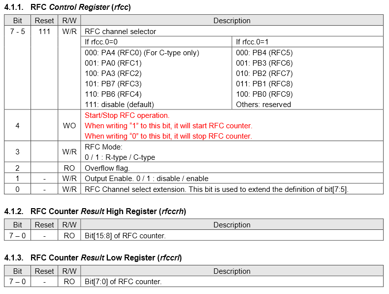
The resistance to frequency converter (RFC) is mentioned as a footnote in Paudaks product line card, but no devices are listed with this feature. A description of the peripheral was found in a data-sheet for a discontinued MCU at a distributor. The document in question was saved here and describes the operation in detail.
This peripheral measures a time constant defined by an externally connected resistor-capacitor pair. It can be used for various sensing applications where a change in resistance or capacitance needs to be measured.
It was noted that the RFC is present in at least the current revisions of PFS154 and PFS173, despite not being mentioned in the datasheet. More details can be found here. The RFC is located at I/O 0x36-0x38 in the PFS154 and 0x2d-0x2f in the PFS173.
The RFC consists of a relaxation oscillator and a 16-bit counter. The frequency of the oscillator is defined by an RC pair connected to a selectable I/O pin. The counter will count the number of pulses after being started by setting a bit in the I/O register. The counter value after a defined time is representative of oscillator-frequency and hence of the RC time constant.
You can find some electrical characterization results and usage examples in this HaD.io project.
11 Bit ADC (PFS173)
Register 0x23, which is part of the ADC peripheral I/O block in the PFS173, is notably absent from the documentation of the I/O space.
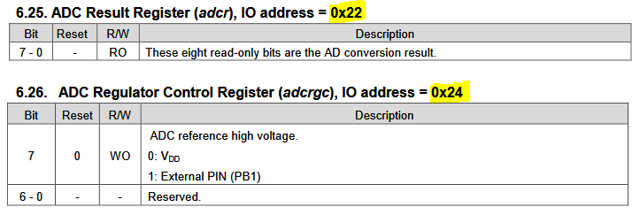
Probing this register shows that bits 7-5 are readable and seem to represent three additional least significant bits of the ADC result. It is not clear why these bits were left undocumented. Possibly they were deemed too noisy, or malfunction under certain settings. More investigation is needed here.
The undocumented register ADCRL can be accessed like this:
	__sfr __at(0x23)         _adcrl;
	#define ADCRL            _adcrl

	uint8_t adcout  =ADCR;			// Read most significant bits
	uint8_t adcoutl =ADCRL>>5; 		// Read three hidden bits
	uint16_t adc=(adcout<<3)|adcoutl;  	// adc contains 11 bit result
Checkout /doc-style for more information on some of the special Markdown formatting features we use.